Can You Keep Driving With Code P0161?
You can typically drive short distances to a qualified repair shop, provided the Check Engine light remains solid and is not flashing. Yes. Downstream sensor only checks emissions performance. However, operating under this condition forces the engine control module into altered fuel or timing strategies, accelerating wear on emissions hardware and reducing power under load. Inspect vital fluids before driving.
What Code P0161 Means
Trouble code P0161 is defined by standard SAE/ISO diagnostic protocols as O2 Sensor Heater Circuit Malfunction (Bank 2 Sensor 2). The engine control computer monitors this circuit and mechanical subsystem continuously through dedicated telemetry sensors. When sensor readings or calculated performance metrics deviate outside calibrated factory boundaries for more than two consecutive drive cycles, the computer records Freeze Frame diagnostic data and illuminates the Check Engine light on your instrument cluster.
How the Heated Oxygen (O2) & Air-Fuel Sensors Operates
Modern vehicles utilize zirconia oxygen (O2) and wideband air-fuel ratio (AFR) sensors to measure exhaust gas composition. The upstream sensor (Bank 1/2, Sensor 1) monitors exhaust before the catalytic converter, generating a voltage that oscillates between 0.1V (lean, excess oxygen) and 0.9V (rich, excess fuel) multiple times per second. The downstream sensor (Sensor 2) monitors post-converter exhaust to verify the catalytic converter is properly storing and releasing oxygen.
Because oxygen sensors cannot generate reliable voltage below 600°F (315°C), they incorporate internal ceramic heating elements controlled by the PCM. When the engine starts cold, the PCM supplies 12V to the heater circuit to reach closed-loop operation in under 30 seconds. If the internal heater filament burns open, wiring harness chafes on the exhaust shield, or silicone sealants poison the sensor tip, the PCM triggers an O2 sensor diagnostic trouble code.
The Most Common Diagnostic Mistake
Don't Replace Sensors Without Inspecting Exhaust Leaks: Before buying a new oxygen sensor, inspect the exhaust pipe upstream of the sensor for pinhole cracks or loose flange gaskets. Exhaust pulses create a venturi vacuum that sucks outside air into the pipe through even microscopic pinholes. This fresh air fools the O2 sensor into reporting a false lean condition, leading owners to replace good sensors while the leak remains.
Common Symptoms & Driving Observations
When code P0161 triggers, drivers typically report one or more of the following physical driving symptoms:
- Check Engine light illuminated: Illuminates steady on the dashboard to warn that onboard telemetry exceeded calibrated limits for two drive cycles.
- Smog inspection failure: Typical driving observation associated with Heated Oxygen (O2) & Air-Fuel Sensors malfunctions under real-world road conditions.
- Engine drives normally with no loss of power: Felt as a flat spot or delayed throttle response when attempting to merge or pass on the highway.
Diagnostic Triage: Likely Causes & First Checks
To avoid spending money on unneeded parts, triage the most frequent failure points starting with the easiest and least expensive DIY checks first:
| Likely Cause | Subsystem | Triage Priority | Diagnostic Action |
|---|---|---|---|
| Burnt heating element in Bank 2 Sensor 2 | Heated Oxygen (O2) & Air-Fuel Sensors | Check First (DIY) | Measure heater circuit resistance across sensor pins with a multimeter. |
| Blown O2 sensor fuse | Heated Oxygen (O2) & Air-Fuel Sensors | DIY Inspection | Check underhood fuses for O2 heater circuit. |
| Damaged wiring harness | Heated Oxygen (O2) & Air-Fuel Sensors | Bench Test | Install new direct-fit Bank 2 Sensor 2. |
| Corroded connector terminals | Heated Oxygen (O2) & Air-Fuel Sensors | Shop Diagnostic | Measure heater circuit resistance across sensor pins with a multimeter. |
Step-by-Step Diagnostic Protocol
Follow this systematic 4-step diagnostic protocol before ordering replacement parts:
Measure Internal Heater Circuit Resistance [Digital Multimeter (Ohms)]
Disconnect the O2 sensor harness connector. Locate the two wires of identical color (usually two white or two black wires for the heater circuit). Measure electrical resistance across those two sensor terminals at room temperature.
Pass/Fail: A healthy heater circuit typically measures between 3.0Ω and 15.0Ω. An open circuit reading (OL / infinite) confirms a burned-out internal heater requiring sensor replacement.
Verify 12V Power and Ground at Harness Connector [Multimeter (DC Volts) / 12V Test Light]
With the ignition key turned ON (engine off), test the vehicle harness side connector. Verify 12V battery power is supplied to the heater wire and the ECM provides a solid ground pulse.
Pass/Fail: Must register full battery voltage (12.2V–12.6V). Zero volts points to a blown O2 heater fuse or relay failure in the underhood fuse box.
Inspect Sensor Wiring Harness for Exhaust Heat Damage [Flashlight & Inspection Mirror]
Trace the sensor wiring harness along the exhaust downpipe, catalytic converter shield, and transmission tunnel. Look for melted wire loom, chafed insulation, or melted copper touching the hot exhaust pipe.
Pass/Fail: Wiring loom must be securely clipped in factory heat-shield brackets with zero melted or frayed insulation.
Monitor Live Sensor Switching Voltage Graph [OBD-II Scanner with Live Graphing Mode]
With engine at operating temperature (195°F), graph Bank 1 Sensor 1 voltage at 2,000 RPM. Upstream zirconia sensors must oscillate rapidly between 0.1V and 0.9V at least once every 1–2 seconds.
Pass/Fail: Upstream sensor should switch crisply. If voltage stays flatlined at 0.45V or responds sluggishly, the sensor is lazy or contaminated.
Estimated Repair Costs: DIY vs Professional Shop
Average repair pricing based on OEM parts, standard labor times, and national independent repair shop rates:
| Repair / Replacement Stage | DIY Parts Only | Independent Mechanic | Dealership Service |
|---|---|---|---|
| Upstream Air-Fuel Ratio Sensor (OEM Denso/Bosch) | $85 – $175 | $220 – $360 | $340 – $520 |
| Downstream Oxygen Sensor Replacement | $55 – $120 | $160 – $260 | $240 – $390 |
| Exhaust Flange Gasket / Manifold Crack Repair | $25 – $65 | $140 – $280 | $260 – $480 |
Related Field Guides & Cost Tools
How oxygen sensors, exhaust restrictions, and fuel trims alter fuel consumption before check engine lights flash.
Calculate your true cost of ownership, compare DIY savings against mechanic labor rates, and estimate your running cost per mile.
Never lose another repair receipt or fuel log
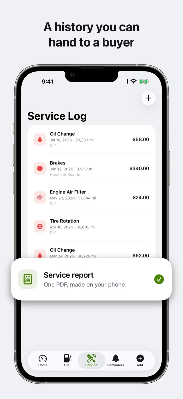
Keep your complete service history, real full-tank MPG, and diagnostic records organized on your iPhone. Carvico alerts you before service is overdue and gives you verified PDF records when you sell — 100% private on your own iCloud with zero ads.
Related Diagnostic Codes
Camshaft Position Actuator Circuit (Bank 1)
Electrical circuit fault in the intake variable valve timing (VVT) solenoid on cylinder Bank 1.
P0011Camshaft Position 'A' Timing Over-Advanced (Bank 1)
The intake camshaft timing on Bank 1 is further advanced than the ECU commanded.
P0012Camshaft Position 'A' Timing Over-Retarded (Bank 1)
The intake camshaft timing on Bank 1 is lagging behind the computer's commanded timing advance.
P0013Exhaust Camshaft Position Actuator Circuit (Bank 1)
Electrical fault detected in the exhaust variable valve timing (VVT) solenoid circuit on Bank 1.